Homemade wine chiller incubator build

LadyHawkeAvry

Songster
Jan 25, 2015
1,049
121
133
Carlisle, NY
I have built several coolerbators, and despite the family buying me a Brinsea, I still have my active coolerbator in constant use. I had grown out of just two incubators, lhowever, and needed to build a third. I decided "Go big or go home", and set my sights on a cabinet. I searched Craigslist for building materials, and was less than thrilled with the results. I had found several non working beverage coolers, all obscenely overpriced, and most wine coolers were too small. After a few months, I finally found a 3.5 cu. ft. Haier wine chiller, which became the base for the build.

Parts:
Wine chiller
Electrical wire
Extension cord or replacement lamp cord with plug
Small transformer plug
Wire conduit
Ceramic light fixtures
60 watt light bulbs
120 mm computer fans
High temperature sealant
2 x 4 x 6
1" wide wood strips (or smaller)
STC-1000 temperature controller
Caulk
assorted screws
Duct tape
clear aquarium tubing
hardware cloth
insulation board
silver solder
wire nuts
shelving or similar material
Rubber gaskets or bushings (small)

Tools:
Dremel with cutoff wheel
drill
circular saw
soldering iron
assorted drill bits
small screwdrivers (both phillips and flat head)
large screwdrivers (both phillips and flat head)
wrenches
vise grips
pipe cutter
drum sander for Dremel
hole saw

Day 1:

The compressor and original thermostat were removed from the cooler. This is best done outside or in a garage with ventilation, as the coolant gas inside the system is toxic and will escape as the lines are cut.

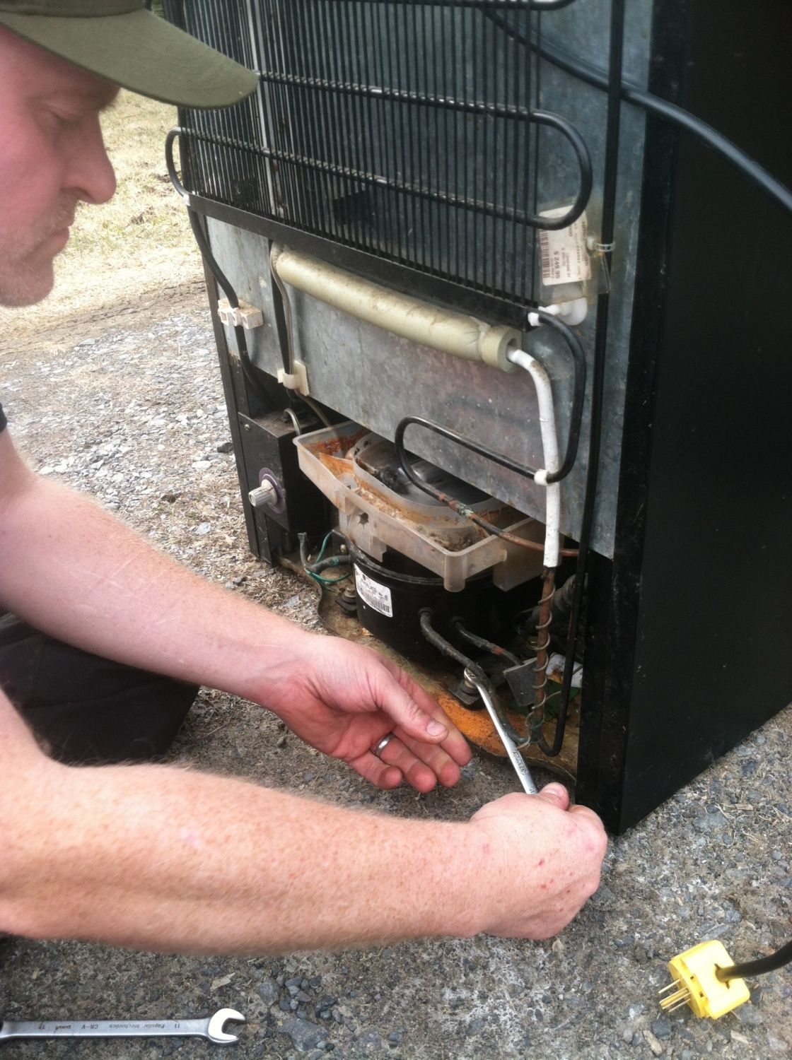
removing the bolts from the compressor

Unhooking the electronics

Removing the thermostat and temperature control unit

With the thermostat and electronics removed, the rear bolts can be accessed

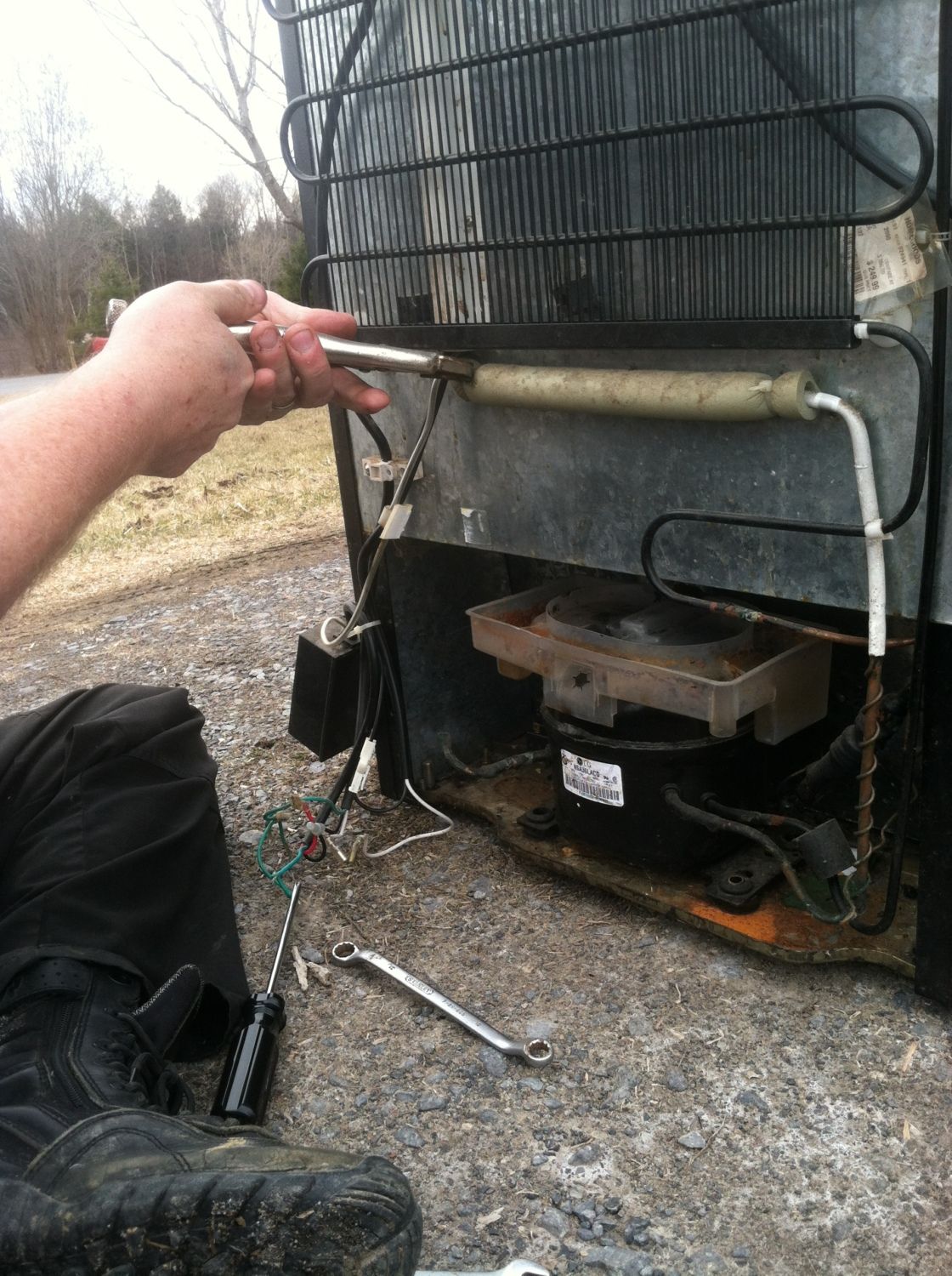
Removing the hoses and insulation

Cutting through the aluminum hoses with a pipe cutter allows for removal of the cooling grille. Freon gas will escape when this line is cut, and breathing it should be avoided.

Once the grille is removed, the remaining lines can be cut and the compressor removed

The remaining hoses and wires can now be removed from the back before starting on the inside

The refrigerator plate from the inside is then removed, and the unit is ready for cleaning.

Once scrubbed and bleached, the cooler was ready to head inside for assembly into an incubator.
 
Last edited:
Day 2:

The cooler has been moved inside for assembly

Basic supplies are ready to go - I ended up not using the stainless hardware on the left because the unit was so thick that those 3" bolts weren't long enough to go through both the cooler and the fans!

MissBehavin ("Missy") says it is time to get to work! The shelves are used to approximate the positions of egg trays

After measuring to find the center point, the fans are traced onto the back of the cooler, a few inches from the top of the interior. I used the level app on my phone to set each fan level as I traced it. Both openings were cut in the metal using the Dremel. I left little tabs of metal in each corner for affixing screws.

Once the holes are cut and the foam insulation removed, I drilled a few small pilot holes to aid me in locating where the holes were from the interior. From the inside of the unit, I cut out the plastic using the holes as guides.

To mount the fans, I used 3" exterior deck screws and rubber grommets. To get the fans to circulate air through the system from the top down, place the side with the label in the center facing the inside of the cooler. I placed the fans where I wanted them, and marked the position of the screws with a sharpie. I then drilled small pilot holes in the sheet metal before screwing the fans in place. To prevent over torquing the fans in any direction (which can break the housing). screw each screw in small increments, and rotate through the screws as you tighten them (much like putting the lug nuts on a car tire)

Both fans are now installed. Computer fans come in various wiring configurations. Here I have both a 3 wire and 4 wire fan. For a 2 wire fan, wire red to the positive side of the transformer wire and black to the negative. For 3 wires, wire red and yellow to positive, and black to negative. For 4 wires, wire red and yellow to positive, and blue and black to negative. If you want your 4 wire fan to run faster, do not connect the blue wire. I connected it since at the higher speed it was a bit noisy, and with a dual fan setup, I didn't need a huge amount of airflow out of a single fan. Solder the connections with silver solder and apply heat shrink tape to the connection to seal.

Cut a small hole in the bottom of the unit for a return vent. I cut this from the inside first because it was easier to reach. I then drilled pilot holes as I did for the fans after removing the insulation, and cut using the guide holes from the rear. I used a small piece of duct tape as a template for my hole. After the hole is cut, trim a small piece of hardware cloth to a size just slightly larger than the lower vent hole. I used duct tape to frame the hardware cloth and affix it over the hole (eventually I will add a few small screws) The hardware cloth keeps any chicks who may possibly get to the bottom of the unit from entering the vent and the rear air duct.

I measured the cooler and cut two pieces of 2 X 4 so that they would sit even with the trim on the top, and hang a few inches down into the recessed area in the bottom. I attached them to the cooler with 3" deck screws. I needed something flexible to create the angle between the lower vent hole and the air channel created by the 2 X 4s. I searched the garage and found an old corrugated plastic sign that had been on my mother's lawn about a decade ago. It was waterproof and flexible. I bent it so that it was flush to the interior of the bottom recessed area in the back of the cooler, and then bent it again before the vent so that it emerged from the recess at an angle. I made a third bend so that the top sat flush on the 2 X 4s. This became the lower portion of the air return duct. I used a short length of 2 X 4 and some additional deck screws to secure the plastic to the base of the cooler below the vent.
I screwed the plastic into the 2 X 4s at the top, and sealed the open corners with duct tape, creating a closed diagonal duct to the air return vent.

For the remaining vent I used foam insulation board I had around. It was old... Really old, so after measuring it and cutting it to fit the remaining portion of the air circulation duct, I sealed the whole thing inside a plastic garbage bag to prevent any particulate matter that could possibly escape from entering and contaminating the incubator.

I secured everything with duct tape, then screwed the wrapped insulation down using 1" exterior screws.

To make a place for the humidity tray, I measured the interior of the cooler and cut a piece of shelving to fit. I cut mine to fit snugly, and had to "persuade" it into position with a rubber mallet.

To install the heat light sockets, I measured the top of the cooler and marked holes for the lights 6" in from each edge. Using a hole saw on the drill, I drilled holes for each socket. Using the dremel and a sanding drum, I trimmed each hole to fit the ceramic socket snugly, then inserted the sockets.

I sealed the interior with high temperature gasket...

...And the exterior. Since the gasket has to sit for 24 hours, this ended day #2
 
Day 3:

The high temperature sealant is now cured enough to work with, and wiring can begin

I traced around the STC-1000 unit to make a template for cutting, then cut a hole in the side of the cooler with the cut off wheel

Using a couple of lengths of wire, I consolidated the two positive and two negative wires from the light sockets into two single wires. I then drilled a hole close to where the thermal control unit was located and threaded both wires into the cooler. I wire the temperature controller by first running all the positive wires, and then running all the negative ones. You will need to cut two small jumper wires for the positive side, and one for the negative.

Here is the basic wiring diagram for the STC-1000. All wires running to slots on the unit should be threaded from the inside of the cooler out to the unit since once it is inserted, it will be difficult to tighten the locking screws that hold the wires in place. Take the positive wire that you threaded into the cooler and put it into the #6 slot. Then run one jumper wire out from slot #5 and another from slot #1. Drill another hole just below the temperature controller hole, and run the positive and negative wires from your plug cord into the cooler. I used the original plug and cord that came with the cooler for this. Connect the positive cord from the plug wire, the jumper wire from slot 1 and the jumper wire from slot 5, and secure them all together with the wire nut. For the negative side, run a single jumper wire from the #2 slot. Connect the negative wire from the lights, the negative wire from the plug cord, and the jumper wire from slot 2 with a wire nut. Place the two ends to the temperature sensor wire into slots #3 and #4. Push the STC-1000 unit into the hole you cut in the side of the cooler. I ran a bead of caulk around the edge of the unit so it fit snugly and looked neat.

The green wire is the ground wire, which will be affixed to the metal side of the cooler. I re-purposed some of the hardware from the back of the cooler, including the rubber grommets and wire keepers to help neaten up the wire install

All exposed wires are encased in conduit

A wire keeper from the back of the cooler was used to tuck all the wiring away from the area where the water tray will sit and the heating lights.

The incubator cords were plugged in, and the unit allowed to cycle overnight before calibration. A plastic tray was placed on the shelf for humidity, and filled with a small bit of water as well.
 
Day 4

A few cups of water in the humidity tray brought the humidity up to about 70%. Too high for incubating, but I had an unplanned, pipped egg in incubator 1, so I used it as a hatcher today. It gave me a day off from the build, and resulted in a healthy khaki campbell duckling.
400

Next step for today is to set up for temperature calibration. I will be placing sealed jars full of water into the incubator at each level to use for regional temperature measurement, and do tray builds and calibration on day 5...
 
Day 5:

Temperature calibration was started. I used the temperature probe on the temp control unit, a temperature probe on the multimeter for spot checks, a thermometer/hygrometer combo unit (known to be about 1.5 degrees C low through previous calibration) and a mercury thermometer submerged in a baby food jar full of water that was allowed to come up to temperature overnight before measurement.
400

Glass/mercury thermometer measurement
The mercury thermometer and the probe on the temperature controller were in agreement. The thermometer/hygrometer was low as expected. I set the temperature probe so that it measured between the two incubating shelves. One will be slightly warm, and one slightly cool with this configuration, but the temperature was not more than 0.5 degrees C off of 37.5 C on either shelf.

The ground wire was also attached at this time. The main power cord was grounded, so the ground wire was isolated and a ring connector was attached. A hole was drilled into the metal side of the cooler and the ground wire was screwed into place.
400

Ring connector attachment
400

The ground wire secured to the chassis
Day 6, construction of slide out trays...
 
Day 6:

Since the cooler was designed for slide out racks, I designed my trays as slide out frames with a hardware cloth base to allow for full air flow. I decided to use prefabricated automatic egg turners on top of the slide out trays since an auto turning unit would be very narrow and any egg racks would have to be restricted to a rather small size and custom cut to fit.
I used small pieces of an old cork board frame for sliders, and 1 X 1s from an old display rack for the frame.
400

The 1 X 1s had been polyurethaned over a decade ago, so I did not have to worry about fumes. I measured the length of the shelf guides and cut my sliders to fit. The actual useable space ran a bit farther back than the shelf guides, so I measured to the back of the cooler, leaving about 1/2" of space in front to allow for door closure. I then measured the interior width, and subtracted the width of my sliders to get the proper length for the pieces from side to side. I made 3 shelves, so I cut six pieces of each for sliders, front to back pieces and side to side pieces. After verifying the pieces fit correctly in the cooler, I used a brad nailer to affix the sliders to the side pieces and to secure the edges of the frame. Once the frames were together, I secured the 1 X 1s with a 3" exterior screw at each corner.
400

Attaching the slider rails
Hardware cloth was then cut to fit and stapled to the bottom of the trays
400

Side view of completed tray showing rails in place
400

Top view of slide in tray
400

3 trays in place

Day 7, final assembly
 
Day 7:

Since I used commercial turners, I had to pick the proper sized turner for the available space. My useable space on my racks was approximately 15.5" by 15", so I settled on the automatic egg turner unit for the Little Giant 10300/9300 incubator series. Since they are designed to just be set into the incubator, the power cords had to be cut, threaded through holes drilled in the side of the cooler, then reattached, soldered, and sealed with heat shrink wrap.
Having run the incubator for over a week, I found that the humidity was too high when the water tray was on top. I hung the tray below the lower egg tray, and added a second dish of water set on top of four 6" X 6" ceramic tiles (my favorite heat sink material). This resulted in a much lower humidity that was favorable for incubation.
The cooler also came with an internal light on a separate switch. I replaced the bulb, cleaned the housing, and wired a short length of extension cord in order to plug the internal light into the power strip for viewing the eggs when the heating lights were off.
I placed the egg trays so that the cords would be on the side as the rest of the power cords that exited the unit. I slid the egg trays out with the turners in place and measured the cord so that it allowed for full extension. I added a few more inches for the cooler wall and cut the cords.
Holes were drilled in the cooler below the egg trays, and the cords from the turners threaded to the outside. The wires were then reattached, silver soldered, and secured with heat shrink wrap on the outside. The configuration allows just enough cord to remain on the inside to allow the trays to slide freely for addition and removal of eggs.

Although there was room for a third tray to be used as a hatcher, I left it out for the moment. The temperature is configured for optimal use with two trays, and incubator 1, which holds humidity best, will become a designated hatcher once it has completed its current incubation run.

The unit was allowed to return to temperature and cycle prior to beginning a test run. Test eggs were placed on both shelves to evaluate hatch rate per shelf.
400

Internal light rewired for use
400

Completed unit with turners installed and test run eggs set.

Next installment after week 1 of test incubation...
 
The incubator has been running long enough to evaluate test hatches - so far:
Khaki campbell: equal development on both shelves. Only eggs older than a month old did not develop.
Moulard: 50% development at first candle. Holderread et al gives moulards a 40% hatch rate.
Ring Necked Pheasant: development in all eggs
Orpingtons: development in all eggs
Guinea fowl: too early to candle

I finished incubation of my last batch of ducks in the incubator, converting incubator 1 to a hatcher. At lockdown, all but 3 eggs were internally pipped. The eggs not pipped had been marked as questionable the week before. Hatch rate on eggs verified as viable prior to transfer into the new incubator was 100%.

Final thoughts: use of a separate hatcher is optimal with this design since the temperature is calibrated optimally for 2 shelves.
A quick connect on the turner trays would be useful to facilitate removal for breakdown and cleaning.

More when the first eggs incubated from set date to lockdown in the new incubator build hit the hatcher in a few weeks!
 

New posts New threads Active threads

Back
Top Bottom